| 1 | Review ground and design conditions | Ground-investigation tools, survey instruments, and design records | Review soil and rock layers, groundwater level, adjacent structures, wall depth, thickness, and excavation sequence. Wall dimensions are project-specific; common thicknesses are approximately 0.6–1.5 m. | Ground conditions and project constraints determine the suitable excavation method, support-fluid plan, and panel sequence. |
| 2 | Set out the wall and build guide walls | Survey equipment, excavator, formwork, and concrete-placement tools | Mark the wall alignment and panel limits. Construct guide walls to control the trench position and provide a stable reference for excavation equipment. | Accurate alignment at the surface helps control verticality and position throughout excavation. |
| 3 | Excavate the panel | Hydraulic grab or hydromill trench cutter, selected for ground conditions | Excavate to the approved panel width, thickness, and founding depth. A grab is commonly used in suitable soils; a cutter can be selected where deeper excavation or harder strata require it. | The right excavation system can improve trench accuracy and productivity while addressing the site's geology. |
| 4 | Support the trench with slurry | Slurry mixing plant, storage tanks, pumps, desander, and testing equipment | Maintain the specified support-fluid level and properties during excavation. Check fluid characteristics, such as density, viscosity, and sand content, against the project specification. | Support fluid helps limit trench collapse and control groundwater inflow before the concrete is placed. |
| 5 | Check trench depth and cleanliness | Depth-measuring device, verticality monitor, and desanding system | Verify excavation depth, panel geometry, verticality, and trench-base condition. Remove excessive sediment and confirm acceptance criteria before reinforcement installation. | Inspection helps reduce defects and ensures the panel is ready for reinforcement and concreting. |
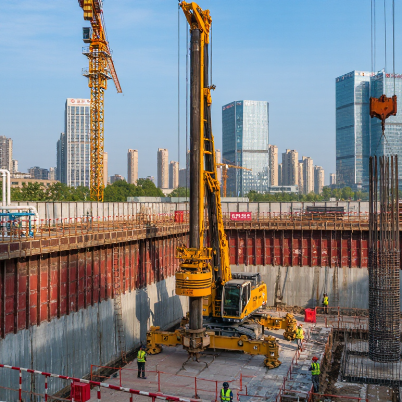
| 6 | Install reinforcement cage and joint form | Crawler crane, lifting frame, reinforcement cage, and stop-end or joint-forming system | Lift and lower the cage using an approved lifting plan. Check cage dimensions, splice details, cover provisions, embedments, and joint alignment against the drawings. | Controlled handling protects the cage and helps maintain the required structural detailing and panel-to-panel connection. |
| 7 | Place concrete by tremie | Tremie pipes, concrete supply vehicles, and concrete testing equipment | Place concrete continuously from the bottom upward through tremie pipes, keeping the discharge embedded in fresh concrete as required by the method statement. Record delivery and placement details. | Tremie placement displaces the support fluid and helps produce a continuous concrete panel under slurry. |
| 8 | Complete, inspect, and proceed to adjacent panels | Survey instruments, concrete records, joint-cleaning tools, and excavation equipment | Record concrete volume and levels, check the finished panel and joints, and follow the approved sequence for primary and secondary panels. Continue with adjacent panels as specified. | Consistent sequencing and documented checks support wall continuity and provide traceability for construction quality. |


 Your message must be between 20-3,000 characters!