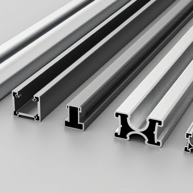
| 1. Standard perimeter frame | Frame depth: about 30–40; visible face width: about 8–15 | Common extrusion choices include 6005-T5 and 6063-T5 | Encloses the module edges, supports the glass-and-laminate assembly, and provides a practical interface for mounting. | Widely adaptable to conventional framed modules; balances stiffness, weight, and material use. | Match the channel and retaining lips to the module stack thickness, sealant or gasket, and corner-joint method. |
| 2. Deep-section perimeter frame | Frame depth: about 40–50; visible face width: about 10–18 | Often specified in 6005-T5 or 6061-T6, depending on design requirements | Provides a deeper section for applications where added frame rigidity or a taller mounting interface is needed. | Greater section depth can improve bending stiffness without requiring a solid section. | More depth may add material and module thickness; structural performance still depends on geometry, alloy, joints, and support spacing. |
| 3. Low-profile perimeter frame | Frame depth: about 25–35; visible face width: about 8–15 | Commonly 6063-T5 or 6005-T5 | Frames modules where a lower edge profile or reduced overall frame depth is preferred. | Can reduce frame height and material compared with a deeper section. | Reduced section depth can limit stiffness; verify structural loads, handling requirements, and mounting compatibility. |
| 4. Wide-lip retaining profile | Frame depth: about 30–40; retaining lip or face width: about 12–20 | Common choices include 6063-T5 and 6005-T5 | Uses a broader retaining face to overlap and secure the module edge, subject to the module’s approved frame design. | Offers a larger contact area for edge retention and can accommodate some assembly designs with wider frame faces. | Keep the retaining geometry clear of the active cell area and ensure it does not create excessive stress on the glass edge. |
| 5. Drainage-channel profile | Frame depth: about 30–45; channel dimensions are design-specific | Commonly 6005-T5 or 6063-T5 | Incorporates a channel or openings intended to help manage water at the module perimeter. | Can provide a defined path for water to exit the frame area when correctly designed and installed. | Drainage details must avoid water traps and remain compatible with the module orientation, seals, and cleaning conditions. |
| 6. Reinforced-corner-compatible profile | Frame depth: about 30–45; internal joint features vary by corner design | Often 6005-T5 or 6063-T5 | Provides internal pockets, grooves, or shoulders designed to work with corner keys or other frame-joining methods. | Supports repeatable assembly and helps keep frame corners aligned. | Corner strength depends on the complete joint, including the key or fastener, fit, tolerances, and assembly process. |
| 7. Mounting-interface-integrated profile | Frame depth: about 30–50; mounting groove or slot is system-specific | Commonly 6005-T5 or 6063-T5 | Includes a groove, channel, or shaped surface intended to engage compatible clamps or mounting hardware. | Can simplify the interface between the module frame and a compatible mounting system. | Check clamp position, engagement, fastener loads, and installation instructions; a profile feature alone does not establish system compatibility. |


 Your message must be between 20-3,000 characters!